The updated version of this standard can be found here.
This document describes the !TEXMAP meta-statement, which contains a set of commands for including texture maps in LDraw files.
!TEXMAP
!:
0 !TEXMAP (START | NEXT) method parameters pngfile
0 !: <geometry1>
<geometry2>
...
0 !TEXMAP FALLBACK
<geometry3>
...
0 !TEXMAP END
The START command indicates that the given texture should be used. (If another texture is currently in use, it is pushed onto a stack for retrieval when an END command is given.) This texture will remain in effect until an END is given or the file in which the START is located ends. The texture will remain active when processing an included file unless overridden within that file.
The FALLBACK command is a section marker. In a TEXMAP supporting application, all geometry lines (whether following the 0 !: comment marker, or presented as standard LDRAW geometry: geometry1 or geometry2 lines) between START and FALLBACK are to be used as geometry and have the texture applied. All geometry between FALLBACK and END are ignored. In applications that don't support TEXMAP, nothing needs to be done, and all non-commented geometry is generated as normal (though the LDRAW parts author should be very cautious not to introduce unintended non-commented geometry lines into the START to FALLBACK section).
In general, the START to FALLBACK section will contain only geometry following the special comment marker 0 !:, and geometry between FALLBACK and END will not. The first set of geometry will be used when textures are active (and the second will be ignored), and vice-versa when TEXMAP is not supported.
NOTE: be cautious (and think through your approach) when including geometry2 lines. This feature is present for use generally in the case where the textured and non-textured FALLBACK geometry are the same. This is a rare occurrence, and normally would not be used.
The END command stops using the current texture and restores the previous texture to current status. This means that nested commands with START will form a stack of textures and the END command will pop those textures. If an END command given in a sub file stops the use of a texture specified in a calling file, then that texture will be restored to use when the sub file is exited.
The NEXT command is a shortcut to make a texture work only for the next 1, 2, 3, 4, or 5 line. It would be equivalent to use the START command and then to place an END command immediately after the next 1, 2, 3, 4, or 5 line (with no FALLBACK possible).
The PNG file represents the texture bitmap to apply. The PNG can be B&W or color, and if an alpha channel exists, it should be applied appropriately (allowing the part color to show through).
Currently, there is only one method that can be used to apply textures: PLANAR. In the future, CYLINDRICAL and SPHERICAL might be added, which is why a method token is included in the command.
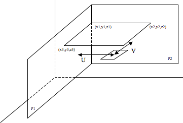
These three points represent 3 corners of the texture map in world coordinates. They form a plane onto which objects can be projected and they also represent the extents of the texture.
In addition, points 1 and 2 represent a plane (P1) perpendicular to the texture where point 1 lies on the plane and the normal to the plane follows the line from point 1 to 2. Similarly points 1 and 3 represent a plane (P2) which is perpendicular to both planes. This plane also contains point 1 but its normal follows the line from point 1 to 3.
Now to map from world coordinates to texture coordinates, U is given by the distance between a point and plane P1 divided by the length of the vector from point 1 to point 2. V is given by the distance between a point and plane P2 divided by the length of the vector from point 1 to point 3. Now U and V are values normalized to between 0 and 1. These can now be mapped to the pixels of the texture map.